Uncategorized
CG Emotron VSM Series AC Drives: Complete Guide to Features, Specifications & Programming
CG Emotron VSM Series AC Drives: Complete Guide to Features, Specifications & Programming
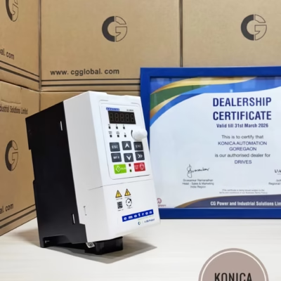
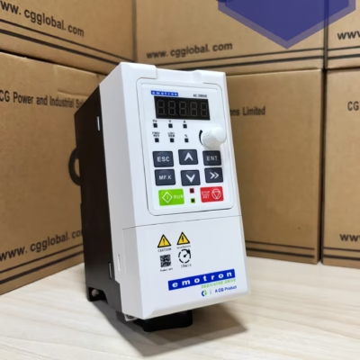
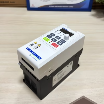
⚡ The VSM series from CG Emotron (CG Drives & Automation) is a compact, cost-efficient variable frequency drive built for everyday industrial automation — fans, pumps, blowers, compressors, conveyors and general-purpose machinery. This guide covers everything from decoding the model number to wiring the drive and getting it running from the keypad.
💡 Main Features
✅ Excellent performance with high start torque characteristic
✅ High-precision torque control — V/f separated control and sensor-less vector control
✅ Optimized, compact structural design on a leading technology platform
✅ Supports both induction motors and permanent magnet motors
✅ Strong overload capability — 200% of rated load for 1 second
✅ Standard rated for operation up to 50°C ambient
✅ Heavy-duty drive suitable for a wide range of applications
✅ Built-in brake chopper
✅ Built-in PLC logic functions, with virtual digital I/Os, multi-logic functions, timers and comparators
✅ Efficient cooling with independent air duct design for improved reliability
📋 Understanding the VSM Model Number
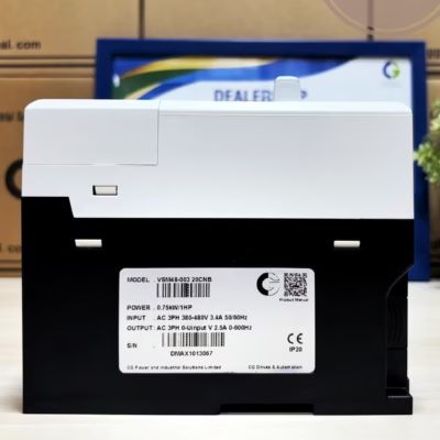
Every VSM drive’s nameplate encodes its specification in the model number. Here’s how VSM48-003-20CEB breaks down:
| Code Position | Meaning |
|---|---|
| VSM | Product series — VSM = Compact machine drive |
| 48 | Input AC voltage level — 380–480V AC / 540V DC |
| 003 / 004 / 006 / 009 | Rated current code (A) — e.g. 003 = up to 2.5A, 009 = 9.5A |
| 20 | Protection class — IP20 |
| C | Control panel — C = Standard panel |
| N / E | EMC filter — N = No filter, E = EMC filter fitted |
| B / – | Brake chopper — B = Brake chopper fitted, – = without |
💡 A ‘-XS’ suffix on the model number denotes a drive with a 7-segment LED display instead of the standard LCD.
⚖️ Available Models & Ratings (3-phase, 415V)
| Model No. | Power (kVA) | Input Current (A) | Output Current (A) | Motor (kW / HP) |
|---|---|---|---|---|
| VSM48-003-20CEB | 1.5 | 3.4 | 2.5 | 0.75 kW / 1 HP |
| VSM48-004-20CEB | 3.0 | 5.0 | 4.2 | 1.5 kW / 2 HP |
| VSM48-006-20CEB | 4.0 | 5.8 | 5.5 | 2.2 kW / 3 HP |
| VSM48-009-20CEB | 6.0 | 11 | 9.5 | 3.7–4 kW / 5 HP |
🔧 Technical Specifications
| Rated input voltage | 3-phase 415V (−20% ~ +20%) |
| Rated input frequency | 50Hz / 60Hz, tolerance ±5% |
| Output frequency range | 0 ~ 600Hz, resolution 0.01Hz |
| Control modes | V/f control, Sensor-less vector control 1 & 2 |
| Speed range | 1:50 (V/f) · 1:100 (SVC1) · 1:200 (SVC2) |
| Speed accuracy | ±0.5% (V/f) · ±0.2% (SVC1 & 2) |
| Torque response | < 10ms (SVC1 & 2) |
| Starting torque | 180% at 0.5Hz (V/f & SVC1) · 180% at 0.25Hz (SVC2) |
| Overload capability | 150% for 60s · 180% for 10s · 200% for 1s |
| Protection functions | Overcurrent, overvoltage, undervoltage, over-temperature, overload |
| Ambient temperature | −10°C ~ 50°C |
| Altitude | 0 ~ 2000m (derate 1% per 100m above 1000m) |
| Relative humidity | 5% ~ 95%, no condensation |
| Efficiency | ≥ 93% at rated power |
| Installation | Wall-mounted or flange mounting |
| Cooling | Fan cooled |
🔌 Wiring the VSM Drive
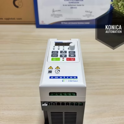
The VSM (0.75–4kW) drive has three wiring zones: the main power circuit, the motor output, and the control terminal block. Getting the wiring right is the first step in programming — the drive can only be configured once it’s powered and the right signals reach the right terminals.
Main power & motor circuit
✅ L1, L2, L3 — 3-phase 415V, 50/60Hz supply, through an MCCB
✅ U, V, W — output to the motor
✅ Earth (⎓) — motor and drive frame earthing
✅ (+), PB — external braking resistor connection
Control terminals
| Terminal | Type | Function |
|---|---|---|
| DI1–DI4 | Digital input | 4 programmable switch inputs — run/stop, direction, preset speeds, etc. Input voltage 9–30V, impedance 2.4kΩ |
| DI7/HI | Digital / pulse input | High-speed pulse input, max 200Hz (100kHz for the D7 variant) |
| AI1, AI2 | Analog input | 0–10V or 0–20mA reference signal — typically used for a speed potentiometer or a 4–20mA process signal |
| AO1 | Analog output | 0–10V or 0–20mA output, e.g. to drive a remote frequency meter |
| Y1 | Digital output | Open-collector output 1, 0–24V / 0–50mA |
| R1A / R1B / R1C | Relay output | Changeover relay contact, 250V AC/3A or 30V DC/1A — commonly wired to a fault indicator or contactor |
| 485+, 485− | RS485 | Modbus communication, 4800–115200 bps — for PLC/SCADA integration |
| +24V, +10V, GND, PE | Power/reference | Onboard supply rails for external switches and the analog reference potentiometer |
⚠️ Always wire and check connections with the drive fully powered down and the DC bus capacitors discharged. Route control wiring separately from the motor power cable to avoid electrical noise affecting the analog signals.
💻 Programming & Commissioning the VSM Drive
There are two ways to configure a VSM drive: the built-in keypad, or CG’s free EmoWizard PC software.
Using the keypad
The standard control panel has a display plus 7 buttons:
▶️ RUN — starts the motor
⏹️ STOP/RST — stops the motor, or resets the drive after a fault
↩️ ESC — exits a menu or cancels an edit
✅ ENT — enters a menu, or confirms an edited value
🔄 MF.K — multi-function key (its action is configurable)
⬆️⬇️ Up / Down arrows — scroll through menus, parameters and digits, or jog the frequency reference up and down
▶▶ >> — shifts which digit you’re editing, or scrolls display pages
💡 Typical first-run sequence: power up the drive → confirm the display shows a frequency (e.g. 50.00Hz) → use ESC/ENT and the arrow keys to navigate into the parameter menu and set the motor nameplate data (rated voltage, current, frequency, poles) → set the command source (keypad, terminal, or RS485) and the frequency reference source to match your wiring → press RUN to test rotation direction at a low frequency, then bring it up to speed with the Up/Down keys.
Using EmoWizard software
For faster commissioning and troubleshooting, CG’s EmoWizard software connects to the drive over USB/RS485 and gives you:
✅ A graphical control panel to start/stop and adjust speed from a PC
✅ A built-in oscilloscope to plot live drive statistics (speed, current, torque) while tuning
✅ Full parameter read/write and comparison, so a working configuration can be saved and copied to other drives
✅ Real-time fault diagnostics
🧩 Accessories
| Accessory | Part No. | Description |
|---|---|---|
| Keypad – basic | PPU-VSmicro | LED display, RJ45 connection |
| Keypad – standard | S-PPU-VSmicro | LCD display, RJ45 connection |
| Profibus card | VSPROFIBUS-DP | Profibus communication card, DB9 connection |
🏭 Typical Applications
✅ Conveyors — material handling and packaging lines
✅ Pumps — water supply, circulation and process pumping
✅ Fans & blowers — HVAC and ventilation systems
✅ Compressors — air and refrigeration compressors
✅ Washing machines & general machinery — anywhere a compact, cost-efficient drive is needed
❓ Frequently Asked Questions
What motors can the VSM drive control?
✅ Both standard induction motors and permanent magnet motors, using V/f control or sensor-less vector control.
Does the VSM series have a built-in braking function?
✅ Yes — it has a built-in brake chopper (the “B” suffix models). You just need to add an external braking resistor for applications with fast deceleration or overhauling loads.
Can the VSM drive be controlled from a PLC?
✅ Yes — via the RS485 (Modbus) port, or through the digital and analog I/O terminals for simple run/stop and speed reference control. A Profibus-DP card is also available as an accessory for Profibus networks.
What’s the difference between the LED and LCD keypad options?
💡 The basic PPU-VSmicro keypad has a simple LED display, while the S-PPU-VSmicro standard keypad has a full LCD display for easier parameter navigation. Both connect via RJ45.
🛒 Shop the CG Emotron VSM Series
🚀 All four VSM models are in stock and ready to ship:
VSM48-003-20CEB — 0.75kW / 1HP
VSM48-004-20CEB — 1.5kW / 2HP
VSM48-006-20CEB — 2.2kW / 3HP
VSM48-009-20CEB — 3.7kW / 5HP